Blog icon

How to Choose the Right PNP Bipolar Transistor?

Choosing the right Pnp Bipolar Transistor requires more than matching a part number to a circuit diagram. A reliable choice begins with the load, supply voltage, switching speed, and available board space. The transistor may control a small indicator, drive a relay, or regulate current in a compact power stage. Each application creates different electrical and thermal demands.

Check the datasheet carefully. Confirm the collector-emitter voltage rating exceeds the circuit’s maximum supply voltage, including possible spikes. Compare the required collector current with the rated value, then allow practical safety margin. Base current also matters. A PNP device usually switches on when its base is pulled below its emitter, but the control signal must remain within its specified limits. This detail is easy to miss.

Package selection affects real-world performance. A small SOT-23 package may suit a sensor board, while a larger TO-220 package can dissipate more heat. Measure the expected voltage drop and power loss, rather than trusting typical values alone. A multimeter can verify pin orientation, but it cannot replace operating tests.

Experience shows that “higher gain” does not always mean “better transistor.” Gain changes with current, temperature, and production variation. Switching circuits may need a firm base drive instead. There is no universal best choice. Recheck the circuit under startup, maximum load, and warm conditions. Even careful selections can overlook wiring resistance or a brief voltage surge. That is why the final decision should combine datasheet evidence, prototype measurements, and advice from qualified engineers.
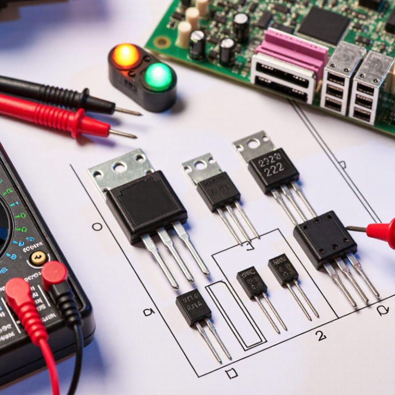
How to Choose the Right PNP Bipolar Transistor?

What Is a PNP Bipolar Transistor and How Does It Work?

A PNP bipolar transistor has three semiconductor regions: p-type emitter, n-type base, and p-type collector. Its emitter usually connects to the positive supply. The collector feeds a load, while the base controls conduction. When the base voltage falls below the emitter voltage by roughly 0.6 to 0.7 volts for silicon devices, the transistor begins to turn on. Conventional current then flows from emitter to collector.

Think of it as a high-side electronic switch. A microcontroller may not drive the base directly if their voltage levels differ. A resistor limits base current and protects the control circuit. With the transistor saturated, the collector-emitter voltage stays relatively low, reducing heat in the device. In active operation, collector current follows base current, but the gain is not a fixed promise. Temperature, current, and production variation change it.

Choose a PNP transistor by checking maximum emitter-collector voltage, collector current, power dissipation, and package temperature limits. Also examine base current, gain at the intended load, and saturation voltage. A device rated for 1 ampere may still overheat in a small enclosure. That detail is easy to miss. On the bench, a diode-test measurement can help identify the emitter-base and collector-base junctions, but it cannot confirm switching performance. Verify the circuit under real load conditions. A common mistake is selecting by current rating alone; thermal behavior often deserves equal attention.

Identify the Electrical Requirements of Your Circuit

Choosing the right PNP bipolar transistor begins with your circuit’s electrical requirements.
Start by defining the supply voltage, load current, and switching frequency. For a high-side switch, the emitter usually connects to the positive rail, while the collector feeds the load. Measure it under load.

Check the transistor’s collector-emitter voltage rating, including possible supply spikes. A small safety margin helps when motors, relays, or long wires create transients. Confirm the maximum collector current and the base-emitter voltage limit.
Never select a device from current rating alone. Thermal behavior matters too.

Base drive requirements deserve careful attention. Use the forced beta specified for switching, rather than trusting a typical gain value. Calculate the base resistor from the available control voltage and required base current.
I once used a typical gain figure and underestimated the resistor’s effect. That shortcut caused slow, unreliable switching. Heat changes everything. Estimate power dissipation from voltage drop and collector current, then check the package temperature under real airflow conditions. For fast switching, review storage time and total switching losses.
A circuit that works on the bench may behave differently inside a warm enclosure.

Compare Voltage, Current, Gain, and Power Ratings

Choosing the right PNP bipolar transistor starts with voltage and current ratings. For a PNP device, the emitter usually sits at a higher potential than the collector. Check the maximum collector-emitter voltage against the circuit’s highest supply voltage, including switching spikes. Leave a safety margin. The collector current rating must exceed the expected load current, not merely match it. Motors, relays, and capacitors may draw sharp startup currents.

Gain, or hFE, also needs careful comparison. It changes with collector current, temperature, and production variation. A transistor rated for high gain at 100 mA may perform differently at 20 mA. Do not design the base resistor around a typical gain value alone. For reliable switching, use a forced gain lower than the datasheet’s typical figure. This reduces surprises, although it increases base current. The choice is not always elegant.

Tips: Check VCEO, IC, hFE, and package limits together. Estimate power with P = VCE × IC during operation. A small package can become hot quickly, even below its headline current rating. Review the thermal resistance and ambient temperature. Test the circuit with the real load, especially during startup. It is easy to overlook heat. Also verify saturation voltage, because a higher voltage drop wastes power and may reduce the load’s available voltage.

Evaluate Switching Speed, Package Type, and Thermal Limits

How to Choose the Right PNP Bipolar Transistor?

A PNP bipolar transistor often serves as a high-side switch, but its switching speed depends on more than the headline frequency. Check turn-on, turn-off, and storage times in the datasheet. Saturation can reduce voltage loss, yet it may trap stored charge and delay turn-off. A strong base drive improves switching, although excessive current wastes power. Measure the actual waveform with an oscilloscope when timing matters. Prototypes can reveal surprises.

Package choice affects both handling and heat removal. Small surface-mount packages save board space, but their limited copper area may raise junction temperature quickly. Larger packages usually dissipate heat better and may tolerate mechanical stress more effectively. Check the package drawing, recommended footprint, and thermal resistance values. A transistor that fits the schematic may not fit the thermal design. That mistake is common.

Estimate power from conduction and switching losses under the real load. Keep the junction temperature below the specified limit, with reasonable derating for enclosure temperature and poor airflow. Copper pours, thermal vias, and short traces can reduce heat buildup. I have found that bench tests under room-temperature conditions can look reassuring, then fail inside a sealed enclosure. Recheck the design at startup, maximum load, and repeated switching. Datasheets are authoritative, but measurements expose assumptions.

Select and Verify the Best PNP Transistor for Your Application

How to Choose the Right PNP Bipolar Transistor?

Select and Verify the Best PNP Transistor for Your Application

Selecting a PNP transistor starts with the load, not the part number. Define collector current, supply voltage, switching speed, gain, and ambient temperature.

WSTS forecast global semiconductor sales at 611.2 billion dollars for 2024. That scale reflects supply complexity, not automatic component suitability. Verify electrical limits from the latest datasheet.

For a high-side switch, check collector-emitter voltage with safety margin. A 24-volt rail should not meet a 25-volt rating. Transient spikes can destroy that assumption. Measure the load current during startup, not only during steady operation. Then calculate base current using the minimum stated gain, rather than the typical value. Keep the base resistor close to the controller output.

Thermal verification needs more than a quick temperature check. Use the datasheet’s junction-to-ambient or junction-to-case resistance. Apply the JEDEC JESD22 testing principles when evaluating temperature and reliability. A transistor may pass on the bench yet fail inside a sealed enclosure. I have made that mistake before. Copper area, airflow, solder quality, and nearby heat sources can change results significantly. Confirm switching waveforms with an oscilloscope, especially during inductive shutdown. Check saturation voltage under the actual base drive. Finally, record voltage, current, temperature, and test duration. Reproducible evidence beats confident selection.