


Blog 
How to Choose the Right Tapered Bearing?
Choosing the right Tapered Bearing involves more than matching a shaft diameter. It requires a clear understanding of the machine’s real operating conditions. A Tapered Bearing supports combined radial and axial loads, making load direction especially important. Speed, shock, temperature, misalignment, and duty cycle also influence performance. In maintenance inspections, early wear often comes from overlooked details. Common examples include incorrect cup-and-cone pairing, excessive preload, poor lubrication, and contamination. A bearing can feel smooth by hand and still run hot under working load. Small errors matter.
Reliable selection begins with verified engineering data, not guesswork. Check the manufacturer’s load ratings, speed limits, dimensional drawings, and recommended fits. Consider the shaft and housing materials, installation method, sealing arrangement, and lubricant viscosity. Clearance or preload must suit the application, because either extreme can shorten service life. Installation quality matters just as much as the bearing itself. Clean tools, correct alignment, and controlled mounting force help prevent hidden damage. Ask for material certificates and batch traceability when reliability is critical. Not every application has a perfect answer. Even careful selection can miss changing loads or harsh site conditions. Review operating temperature, vibration, and wear after installation. That feedback may reveal a better choice. A practical decision combines standards, supplier expertise, field evidence, and honest reassessment.
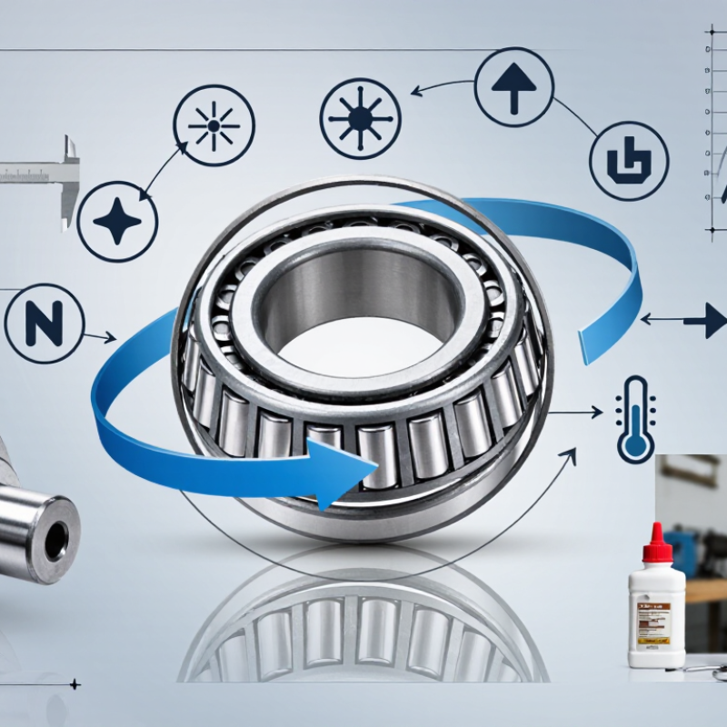
Understanding Tapered Bearing Design and Operating Principles
How to Choose the Right Tapered Bearing?
Understanding Tapered Bearing Design and Operating Principles
A tapered bearing uses a cone-shaped inner raceway, outer raceway, and rollers. Their angled surfaces meet at one projected point on the shaft axis. This geometry lets the bearing carry radial loads and axial loads together. The contact angle controls much of this behavior. A larger angle usually improves axial capacity, but it can increase friction and heat.
The bearing must be chosen for the real operating conditions. Check the radial load, thrust load, speed, temperature, and expected service life. Shaft and housing accuracy matter too. Even a strong bearing can run poorly inside a distorted housing. During inspection, look for uneven roller marks, dark lubricant, or scoring on the raceways. These details often reveal misalignment or poor lubrication before serious damage occurs.
Preload also deserves careful attention. Too little clearance may create heat, noise, and early fatigue. Too much clearance can cause vibration and unstable shaft movement. The calculation is not always clean. Real machines experience shock loads, contamination, and changing temperatures. A careful installer measures endplay after fitting and checks rotation by hand. It should feel smooth, not tight or gritty. Seal condition, lubricant quantity, and adjustment method should match the equipment’s actual environment. One detail is easy to miss: bearing life depends on the complete assembly, not the bearing alone.
| Selection Dimension | Design or Operating Data | Why It Matters | Practical Selection Guidance |
|---|---|---|---|
| Basic Construction | A tapered roller bearing consists of an inner ring, outer ring, tapered rollers, and a cage. | The conical geometry allows the rolling elements and raceways to share a common apex when extended. | Confirm that the complete cup-and-cone assembly is compatible; the inner ring and rollers are commonly supplied as one assembly, while the outer ring is separate. |
| Primary Load Capability | Designed to support combined radial loads and axial loads in one direction. | Load capacity is created by the line contact between the tapered rollers and raceways. | Use a single bearing when the axial load direction is known. Use a matched pair or another opposed arrangement when axial loads can reverse. |
| Axial Load Direction | A single tapered bearing normally carries thrust in only one direction. | The roller-raceway geometry produces an axial force component that must be reacted by another bearing or locating feature. | For two-direction thrust, consider face-to-face, back-to-back, or tandem arrangements according to stiffness, space, and load requirements. |
| Contact Geometry | The rollers and raceways are tapered rather than cylindrical. | The taper converts part of the radial loading into an axial component and provides high combined-load capacity. | Choose the bearing angle and internal geometry from the required radial-to-axial load ratio, speed, stiffness, and adjustment method. |
| Radial Load | Well suited to moderate-to-heavy radial loads, subject to the bearing series and operating conditions. | Line contact gives a larger effective contact area than point-contact rolling elements under comparable conditions. | Check the basic dynamic load rating, basic static load rating, load spectrum, shock level, and required fatigue life. |
| Axial Load | Axial capacity increases with the effective contact angle, but the exact capacity depends on the complete bearing geometry. | A larger contact angle generally increases thrust-carrying ability while increasing the axial component generated by radial load. | Do not select by contact angle alone. Verify manufacturer-neutral load ratings, equivalent dynamic load, static safety, and bearing arrangement. |
| Bearing Arrangement | Common arrangements include single-row, paired, and multi-row configurations. | Arrangement controls axial load capacity, stiffness, preload, thermal behavior, and shaft location. | Use a single row for one-direction thrust; use opposed pairs or multi-row designs when higher stiffness or bidirectional thrust capacity is required. |
| Internal Clearance | Operating clearance is influenced by initial setting, mounting interference, temperature, elastic deflection, and lubrication. | Excessive clearance can reduce stiffness and cause impact loading; insufficient clearance can create overheating and premature damage. | Specify the required setting or preload method rather than selecting clearance in isolation. Account for shaft and housing thermal expansion. |
| Preload | Preload removes internal looseness and can improve rigidity and running accuracy. | Too much preload increases friction, heat generation, and power loss. | Apply preload only when the application requires increased stiffness, reduced deflection, or improved positioning. Validate temperature and torque during testing. |
| Speed Capability | Speed capability is affected by bearing size, cage design, lubrication, load, preload, and operating temperature. | Tapered roller bearings generally generate more sliding and heat than many comparable point-contact bearing designs. | Use the permissible-speed guidance for the selected geometry and lubricant. Reduce speed limits when preload, heavy load, or poor cooling is present. |
| Lubrication | Oil and grease are both used; oil generally provides better heat removal at high speed. | Lubrication separates contacting surfaces, removes heat, and protects against wear and corrosion. | Select lubricant viscosity and consistency based on speed, load, temperature, contamination, sealing, relubrication interval, and compatibility. |
| Operating Temperature | Temperature depends on speed, load, preload, lubricant, seals, ambient conditions, and heat dissipation. | High temperature can reduce lubricant life, alter internal setting, and accelerate material degradation. | Check dimensional changes caused by thermal expansion and use heat-resistant materials or lubricant when the application requires them. |
| Mounting Fit | The shaft and housing fits determine load-zone support, creep resistance, and internal setting after installation. | An incorrect interference fit can distort the rings or change the intended clearance. | Define shaft diameter, housing bore, tolerance class, roundness, shoulder geometry, and mounting method before final selection. |
| Adjustment Method | Axial adjustment is commonly used to establish endplay or preload in opposed tapered-bearing arrangements. | Correct adjustment controls stiffness, friction, temperature, and service life. | Follow a controlled setting procedure using measured torque, axial displacement, temperature, or endplay. Avoid relying only on nut position. |
| Static Load Safety | The basic static load rating is used to evaluate permanent deformation risk when the bearing is stationary or operating at very low speed. | Shock loads and vibration can produce indentations even when calculated fatigue life is adequate. | Check the static safety factor for peak loads, impact, oscillation, transport conditions, and standstill vibration. |
| Dynamic Bearing Life | For roller bearings, the commonly used basic rating-life relationship is L10 = (C/P)10/3 million revolutions. | L10 represents the life at which 90% of an identical group of bearings is expected to reach or exceed the calculated rating life under defined conditions. | Use the equivalent dynamic load P, dynamic load rating C, actual duty cycle, speed, lubrication, contamination, and reliability target in the calculation. |
| Contamination Control | Dirt, water, and abrasive particles can substantially reduce bearing life. | Contaminants damage raceways, rollers, and lubricant films and may initiate surface fatigue. | Use suitable seals, shields, labyrinths, clean assembly practices, filtered lubricant, and appropriate maintenance intervals. |
| Misalignment | Tapered roller bearings require controlled alignment between the shaft, housing, and raceways. | Misalignment creates uneven load distribution, edge stress, heat, and accelerated wear. | Control shaft and housing alignment, shoulder squareness, mounting runout, and structural deflection. |
| Material and Hardness | Bearing rings and rollers are normally manufactured from hardened bearing steel or application-specific high-performance materials. | Hardness, cleanliness, heat treatment, and surface finish affect fatigue resistance and wear performance. | For severe temperature, corrosion, electrical, or contamination conditions, evaluate special material or coating requirements separately. |
| Dimensional Compatibility | The essential dimensional references are bore diameter, outside diameter, total width, cup width, cone width, and shoulder dimensions. | These dimensions determine whether the bearing fits the shaft, housing, spacer, seal, and adjacent components. | Verify all boundary dimensions and interchange requirements from the applicable bearing specification or engineering drawing. |
| Cage Considerations | The cage maintains roller spacing and guides the rollers through the loaded and unloaded zones. | Cage design influences friction, lubricant distribution, speed capability, and resistance to vibration. | Select the cage type according to speed, load, temperature, lubrication, shock, and chemical compatibility. |
| Best-Fit Applications | Typical applications include wheel hubs, gearboxes, axles, transmissions, industrial reducers, and heavy rotating equipment. | These systems often combine substantial radial loading with controlled axial positioning. | Confirm the duty cycle, shock loading, reversing thrust, speed range, environment, maintenance plan, and available installation space. |
| Final Selection Checklist | Required inputs include load magnitude and direction, speed, life target, temperature, lubrication, fit, clearance or preload, contamination, and mounting arrangement. | A bearing that matches only the shaft diameter may still fail because of incorrect load direction, setting, lubrication, or operating temperature. | Compare calculated life, static safety, speed, thermal behavior, stiffness, serviceability, and total installed cost before approval. |