Blog icon

How to Choose a Throttle Pedal Sensor?

Choosing a Throttle Pedal Sensor is not simply a matter of matching a connector. The part translates pedal movement into an electrical signal, so accuracy, response stability, and safety matter every time the vehicle moves. A poor choice may cause hesitation, warning lights, uneven acceleration, or reduced-power operation. Small differences in mounting angle can matter.

Automotive controls engineer Dr. Erik Coelingh emphasizes a useful principle: “Reliable vehicle control begins with trustworthy sensor feedback.” That idea applies directly to the Throttle Pedal Sensor. Buyers should verify the vehicle’s make, model, engine, production year, connector design, signal range, and mounting points. A sensor that looks identical may still send an incompatible voltage signal. It may fit physically but fail electronically.

Look closely at the details.

Check whether the sensor uses dual-channel output. Compare manufacturer specifications, not only marketplace photographs. Examine terminal quality, housing strength, sealing, and return-spring performance. In dusty workshops or humid climates, protection against contamination becomes especially important. For fleet vehicles, documented testing and stable supply are valuable because one failed component can interrupt daily operations.

A practical installation check should include smooth pedal movement, stable readings, and fault-code inspection. Do not ignore minor signal jumps. They can become serious later. I have found that many selection mistakes come from rushed identification, not complicated engineering. Still, specifications alone are not enough. Supplier traceability, warranty terms, and technical support deserve equal attention when choosing a dependable Throttle Pedal Sensor.
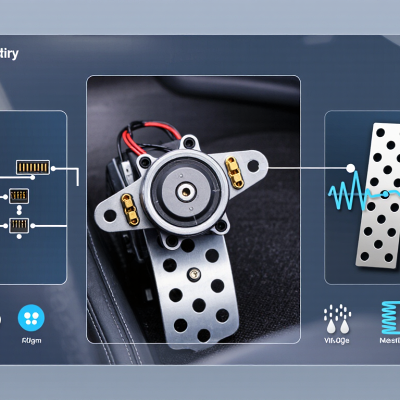
How to Choose a Throttle Pedal Sensor?

Define Sensor Types: Contact, Hall-Effect, and Dual-Track TPS Designs

How to Choose a Throttle Pedal Sensor?

Define Sensor Types: Contact, Hall-Effect, and Dual-Track TPS Designs

A throttle pedal sensor converts foot movement into an electrical signal for engine or motor control. Contact sensors use sliding resistive tracks. They are simple and inexpensive, but dust, vibration, and wear can create signal noise. In a workshop, that noise may appear as small jumps during slow pedal movement. That detail matters.

Hall-effect sensors measure magnetic-field changes without physical contact. Their sealed structure reduces mechanical wear and usually supports smoother, repeatable output. MarketsandMarkets reported that the global automotive sensors market could grow from about 33.7 billion dollars in 2024 to 54.1 billion dollars by 2030. This growth reflects rising demand for reliable electronic control, not proof that every Hall-effect unit is superior.

Dual-track TPS designs add two independent signal channels. The control unit compares their voltage curves and detects disagreement. This design supports diagnostic coverage, especially when a pedal moves near idle or full demand. A 2024 Fortune Business Insights report valued the automotive sensors market at approximately 28.6 billion dollars and projected continued growth through 2032. These figures cover many sensor categories, so applying them directly to pedal sensors would be careless.

For selection, check signal redundancy, operating temperature, connector sealing, and calibration stability. Contact types may suit simple, cost-sensitive equipment. Hall-effect types fit harsh environments better. Dual-track designs deserve attention where fault detection is critical. Do not choose by price alone. I would also test the sensor with real pedal sweeps, because a clean datasheet can hide an uneven response.

Match Output Signals to ECU Standards: 5 V Reference and 0.5–4.5 V Range

How to Choose a Throttle Pedal Sensor?

The ECU must receive a clean, predictable signal. A common design uses a regulated 5 V reference and a 0.5–4.5 V output range. The 0.5 V lower limit leaves diagnostic space for open circuits and shorted signals. The 4.5 V upper limit provides similar protection near full travel. SAE J1843 remains a useful engineering reference for electronic throttle control systems. ISO 26262 also emphasizes plausibility checks, signal monitoring, and fault detection in safety-related electronics.

In practical testing, measure the sensor at rest, halfway, and full depression. The voltage should rise smoothly, without sudden steps or noisy drops. Many pedal assemblies provide two channels, often with different slopes or inverse behavior. This helps the ECU detect disagreement.

A perfect datasheet result can still fail inside a vehicle. Wiring resistance, ground offsets, and connector vibration matter. I have seen stable bench readings become irregular after heat and movement. That detail is easy to underestimate.

Tips: Confirm the ECU’s exact input window before ordering. Check whether it needs one channel or two. Use a calibrated multimeter and an oscilloscope when possible. Record readings across temperature changes. Do not assume every 5 V sensor reaches exactly 4.5 V. Tolerance must be reviewed. Complementary outputs need separate plausibility limits, not guesswork.

Check Accuracy, Linearity, and Redundancy Under ISO 26262 Safety Requirements

How to Choose a Throttle Pedal Sensor?

Check Accuracy, Linearity, and Redundancy Under ISO 26262 Safety Requirements

Check Accuracy, Linearity, and Redundancy Under ISO 26262 Safety Requirements

A throttle pedal sensor must report driver input accurately across its full travel. In testing, I compare measured output with mechanical pedal position at several temperatures. Small errors near idle can cause hesitation or unwanted torque requests. Check repeatability, offset drift, resolution, and response time. Do not trust a single accuracy figure from a datasheet.

Linearity deserves equal attention.

A sensor may appear precise at the endpoints but deviate in the middle. Plot the actual voltage or digital output against pedal angle. Look for smooth progression, dead zones, sudden steps, and hysteresis after release. These details affect plausibility checks and torque control. One overlooked issue is connector movement during vibration testing. It can imitate sensor failure.

Redundancy is central to an ISO 26262 safety case.

Select two independent sensing channels with different output ranges or opposing signal behavior. The control system should detect disagreement, stuck signals, open circuits, and implausible changes. Hardware separation matters, but it is not automatically sufficient. Review diagnostic coverage, fault reaction time, and safe-state behavior within the vehicle architecture. Ask for traceable validation records, including temperature, humidity, vibration, electrical transients, and endurance cycles. Evidence matters.

A practical concern remains: dual channels can share the same mechanical failure.

Check whether contamination, wear, or shaft damage can affect both outputs. ISO 26262 does not make a component safe by itself. The complete system, its assumptions, and its verification determine the real result.

Compare Environmental Ratings: -40°C to 150°C and IP67 Protection

When choosing a throttle pedal sensor, check its environmental ratings before comparing response speed or output signals. A working range from -40°C to 150°C suits demanding engine compartments and severe seasonal conditions. However, the rating must cover the complete sensor assembly, not only the sensing element.

Temperature changes can affect resistance, signal accuracy, and material strength. Ask for test data at both temperature extremes, including thermal cycling results. A sensor may operate at 150°C, yet its connector or cable could age faster nearby. That detail is easy to miss.

During practical inspections, examine cable routing, sealing points, and mounting distance from heat sources. Small installation choices can reduce long-term reliability.

IP67 protection means the enclosure resists dust and temporary water immersion under defined test conditions. It does not automatically withstand high-pressure washing, continuous submersion, or water entering through an unsealed connector. Check whether the connector has matching seals and whether the cable exit prevents capillary water movement. I would also review vibration testing, condensation behavior, and signal stability after repeated temperature changes. Lab ratings are useful, but real vehicles face dirt, splash, vibration, and imperfect maintenance. A careful selection process should compare all of these conditions with the actual operating environment.

Verify Mechanical Fit, Calibration, Connector Pinout, and Service Life

Choosing a throttle pedal sensor starts with mechanical fit, not catalog appearance. Check mounting holes, pedal angle, shaft travel, and surrounding clearance. The sensor must reach its full range without binding. A connector that fits loosely can create intermittent signals under vibration. I once accepted a nearly matching housing and overlooked a slight shaft offset. The pedal returned slowly. That shortcut was wrong.

Calibration requires a stable reference and the correct service procedure. Measure the signal at closed and fully pressed positions, then watch for a smooth voltage change. Do not rely on wire colors. Verify every connector cavity against an accurate pinout diagram. Some systems use dual signal channels, so compare their response and check for unreasonable differences. A scan tool can reveal dropouts that a quick meter test misses. Service life also depends on sealing, dust exposure, pedal cycles, and connector strain. Look for an environmental rating suitable for the vehicle’s location. Inspect the return mechanism, terminals, and harness routing during installation. Keep sharp bends away from the connector. Allow enough slack for pedal movement. I would also record the initial readings, because memory is unreliable during later troubleshooting. Calibration may appear acceptable at room temperature, yet drift after heat and vibration. Test conditions matter.

How to Choose a Throttle Pedal Sensor?

Verify mechanical fit, calibration, connector pinout, and service life before installation.

This reference waveform represents a common dual-channel throttle-pedal sensor design. Channel A increases from approximately 0.5 V to 4.5 V, while Channel B decreases from approximately 4.5 V to 0.5 V as pedal position rises. Actual voltage limits, connector pinout, mounting dimensions, calibration procedure, and service-life rating must be confirmed against the vehicle or equipment specification.

Mechanical Fit
Check mounting holes, pedal travel, clearance, and return-spring alignment.
Calibration
Confirm the idle and full-travel voltage range and required relearn procedure.
Connector Pinout
Verify power, ground, signal, and redundant signal terminals before wiring.
Service Life
Review cycle rating, environmental sealing, vibration resistance, and temperature range.