Blog 
What Are Circuit Breaker Parts and How Do They Work?
Circuit breakers protect electrical systems by interrupting current when danger appears. Their operation may seem simple, but each internal component has a specific purpose. Circuit Breaker Parts include contacts, trip units, arc chutes, terminals, springs, and insulated housings. Together, they detect faults and create a controlled opening in the circuit.
The contacts carry normal current through metal connection points. When an overload or short circuit occurs, the trip unit releases the operating mechanism. The contacts then separate quickly. An arc may form between them. The arc chute divides, cools, and extinguishes that electrical discharge. This action helps prevent heat, fire, and equipment damage.
The mechanism must work fast. It must also close reliably after a qualified inspection. Thermal-magnetic breakers respond to different fault conditions. Electronic trip units can provide more precise monitoring and adjustable protection. Terminals connect the breaker to conductors, while the enclosure provides insulation and physical protection. Small parts matter.
In practical maintenance, technicians check loose terminals, discoloration, unusual smells, and damaged insulation. These details can reveal overheating before failure occurs. However, visual inspection cannot confirm every internal condition. That limitation deserves attention. Manufacturers use different designs, ratings, and terminology, so parts should match the exact breaker model. Product documentation and applicable standards remain essential references. A trained professional should verify installation, testing, and replacement decisions. This guide explains how common Circuit Breaker Parts work, while recognizing that real systems require careful measurement, proper tools, and responsible judgment.
Circuit Breaker Parts: Names, Functions, and Basic Structure
What Are Circuit Breaker Parts and How Do They Work?
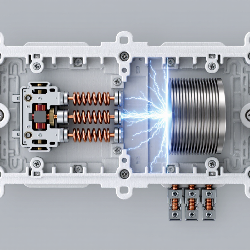
A circuit breaker has several parts working together inside a compact enclosure. The line terminal receives incoming power, while the load terminal sends protected power onward. Movable and fixed contacts carry current during normal operation. When a fault occurs, the trip unit detects excessive current and releases the operating mechanism. The handle then moves, and the contacts separate quickly.
Common trip units include thermal-magnetic and electronic designs. A thermal element responds to prolonged overloads, while a magnetic element reacts to sudden short-circuit current. An arc chute divides and cools the electrical arc after contact separation. The enclosure provides insulation and mechanical protection. In field inspections, technicians also check terminal tightness, contact wear, and signs of overheating. The neat diagram is not the whole story. Real panels are less tidy.
Tips: Turn power off before inspection, and verify isolation with a suitable tester. Never judge condition by the handle position alone. A breaker can look normal while its terminals show heat damage. Match the breaker’s rating with the conductor size and installation requirements. When uncertain, use the equipment documentation and ask a qualified electrician. One small mistake matters.
How Circuit Breakers Detect and Interrupt Fault Currents
Circuit breakers detect fault currents through coordinated parts, not through one magical component. A thermal element responds to sustained overloads. It bends as heat builds in a metal strip. A magnetic trip unit reacts much faster to a short circuit. A strong current creates a magnetic field, which moves a plunger and releases the operating latch.
The latch opens the contacts when the current exceeds a designed threshold. The contacts separate within a short interval. An electric arc forms between them. Arcs are dangerous. An arc chute divides and cools the arc through metal plates, helping extinguish it safely. In some modern breakers, electronic sensors measure current continuously. Their control circuit can distinguish overloads, short circuits, and certain leakage conditions.
The interrupting process depends on timing, calibration, and installation quality. A breaker must interrupt the available fault current without welding its contacts together. That rating matters. Loose connections can create heat before the breaker detects a problem. This is an often-missed weakness. During field inspections, technicians check terminal torque, enclosure condition, and trip operation rather than trusting the label alone. A test may also reveal delayed tripping or mechanical stiffness. No detector is perfect. Temperature, aging, and repeated faults can affect performance. Proper selection and periodic testing keep the sensing and interruption chain dependable.
What Are Circuit Breaker Parts and How Do They Work?
How circuit breakers detect and interrupt fault currents
This representative 50 Hz low-voltage event shows a 20 A load current rising to approximately 800 A during a short circuit. The magnetic trip mechanism detects the high fault current, releases the mechanism, and separates the contacts. The arc chute then helps extinguish the electrical arc, reducing the current to zero. Actual pickup levels and interruption times vary by breaker rating and design.
The Operating Sequence from Fault Detection to Circuit Disconnection
A circuit breaker is more than a switch. It combines terminals, trip units, contacts, springs, and an arc-control chamber.
The line terminals carry normal current into the breaker. Thermal elements respond to sustained overloads by heating and bending. Magnetic elements react almost instantly to severe short-circuit current. Electronic trip units measure current through sensors and issue a trip signal. This is the detection stage.
When fault current exceeds the selected threshold, the trip unit releases a mechanical latch. The latch frees stored spring energy inside the operating mechanism. The moving contact then separates from the fixed contact, often within milliseconds.
An electrical arc forms between them. It is small, but extremely hot. The arc chamber divides and cools this path through metal plates or insulating barriers.
As the arc loses energy, the current stops flowing through the main circuit. The sequence is fast.
After interruption, auxiliary contacts may indicate the breaker’s position to a control system. A technician should inspect contact surfaces, terminals, and the trip indicator before resetting the device.
Testing usually includes insulation checks, mechanical operation, and trip-time verification under applicable electrical standards.
A reset handle does not prove the original fault has disappeared.
The sequence looks precise on paper, but field conditions are less tidy. Dust, moisture, loose connections, and repeated faults can change performance. No breaker is magic. Its reliability depends on correct ratings, installation, maintenance, and honest test results.
Key Differences Between Thermal, Magnetic, and Electronic Trip Parts
What Are Circuit Breaker Parts and How Do They Work?
A circuit breaker combines fixed contacts, moving contacts, an arc chute, and a trip unit. The contacts carry normal current. When a fault occurs, the trip unit releases the operating mechanism. The arc chute then divides and cools the arc, limiting damage inside the enclosure. NFPA’s Electrical Fires report, covering 2015–2019, recorded about 32,620 U.S. home fires annually involving electrical distribution and lighting equipment. These figures make correct trip selection more than a specification exercise.
Thermal trip parts use a bimetal strip. Excess current heats the strip, causing delayed operation. This suits overloads, such as a motor drawing too much current for several minutes. Magnetic trips use an electromagnetic coil. A high fault current creates an almost immediate release, often within milliseconds. That speed helps protect conductors during short circuits. However, magnetic protection alone may miss a modest, persistent overload.
Electronic trip parts measure current through sensors and process the signal digitally. They can provide adjustable long-time, short-time, instantaneous, and ground-fault settings. This flexibility supports large switchboards and changing loads. Electronic units also require more careful testing and auxiliary power planning. No trip method is perfect. A thermal element may respond slowly in a cold enclosure, while an electronic unit can be misconfigured. IEC 60947-2 requires circuit breakers to meet defined performance and verification requirements, but installation conditions still matter. In practice, engineers should compare conductor size, fault current, ambient temperature, and coordination studies before choosing the trip technology.
What Are Circuit Breaker Parts and How Do They Work? - Key Differences Between Thermal, Magnetic, and Electronic Trip Parts
| Comparison Dimension | Thermal Trip Part | Magnetic Trip Part | Electronic Trip Part |
|---|---|---|---|
| Primary sensing element | A bimetal strip that bends as heat builds up from current flow. | An electromagnetic coil and armature that respond to a strong current. | Current sensors, signal-processing circuitry, and a programmed trip unit. |
| Main protection function | Protects against sustained overloads that produce excessive heat in conductors. | Protects against short circuits and very high fault currents. | Provides configurable overload, short-circuit, and sometimes ground-fault protection. |
| Typical trip response | Inverse-time response: a small overload takes longer to trip than a larger overload. | Very fast response, often within milliseconds when current exceeds the magnetic threshold. | Fast and controlled response determined by programmed time-current settings. |
| Dependence on temperature | High. Ambient temperature and heat from nearby devices can affect trip timing. | Low compared with thermal operation, although the complete breaker may have temperature limits. | Generally low for measurement accuracy, but electronics require operation within their specified temperature range. |
| Overload protection | Yes; well suited to protecting circuits from prolonged moderate overcurrent. | Usually not intended to provide precise sustained-overload protection by itself. | Yes; pickup current and delay settings can often be adjusted. |
| Short-circuit protection | Limited when used alone because thermal action is relatively slow. | Yes; designed to operate rapidly when a severe fault creates a high current. | Yes; instantaneous or short-delay functions can be configured according to the protection design. |
| Adjustability | Usually fixed or only minimally adjustable in compact breakers. | May be fixed or adjustable, depending on the breaker design. | Typically offers the greatest adjustment range for long-time, short-time, instantaneous, and ground-fault functions. |
| Power requirement | Self-powered by the heat generated from the protected current. | Usually self-powered by the magnetic field produced by the fault current. | May use energy from the line current, an internal power supply, or an external control source, depending on design. |
| Common applications | General branch circuits, small distribution panels, heaters, lighting, and equipment with predictable loads. | Circuits requiring rapid interruption of high fault currents, including motor and distribution applications. | Large distribution systems, industrial switchboards, data facilities, and installations requiring coordination or monitoring. |
| Coordination capability | Basic coordination is possible, but timing can vary with temperature and load history. | Useful for fast fault clearing, but fixed magnetic thresholds may limit selectivity. | High coordination potential through adjustable pickup levels and intentional time delays. |
| Monitoring and communication | Normally provides no built-in measurement or communication functions. | Normally provides no built-in measurement or communication functions. | May measure current, record trip information, provide alarms, and support communication through compatible accessories. |
| Key advantages | Simple, economical, dependable, and effective for ordinary overload protection. | Very fast operation and strong performance during high-current faults. | Precise settings, improved selectivity, advanced protection functions, and useful system data. |
| Key limitations | Slower operation, temperature sensitivity, and limited adjustment. | Less suitable for accurate long-duration overload protection when used without a thermal or electronic function. | Higher cost, greater design complexity, and possible dependence on electronic power and settings. |
| Typical trip-part combination | Often combined with a magnetic element in thermal-magnetic breakers. | Often combined with a thermal element to provide both overload and short-circuit protection. | May replace thermal-magnetic sensing in larger breakers and can include multiple protection functions in one trip unit. |
Note: Actual trip times, adjustment ranges, interrupting ratings, and available functions depend on the breaker design, rated current, system voltage, and applicable electrical standards.
How to Choose, Inspect, and Replace Circuit Breaker Components
Circuit breaker parts deserve careful attention because each component controls a different failure risk. The handle operates the mechanism, while the trip unit responds to overloads and short circuits. Contacts carry current, and the arc chute helps extinguish dangerous electrical arcs. Terminals secure conductors, while the bus connection transfers power from the panel.
Choose a replacement by matching voltage, pole count, interrupting rating, trip characteristics, and conductor capacity. The replacement must also fit the panel’s approved configuration. A higher rating is not automatically safer. It may allow excessive current through undersized wiring.
A qualified electrician should verify compatibility and de-energize the circuit before inspection. Never rely on the handle position alone.
Inspect for melted insulation, darkened plastic, loose terminals, buzzing, or a hot panel cover. Repeated tripping needs investigation. It is not a nuisance.
The National Fire Protection Association reported an estimated 32,680 U.S. home fires involving electrical distribution and lighting equipment from 2016 to 2020. These fires caused approximately 470 civilian deaths, 1,100 injuries, and 1.3 billion dollars in property damage, according to its Home Structure Fires report.
Replace damaged breakers with correctly rated components, not improvised substitutes. One field mistake still occurs: replacing the breaker without finding the overload source. Sometimes the breaker is doing its job.
